
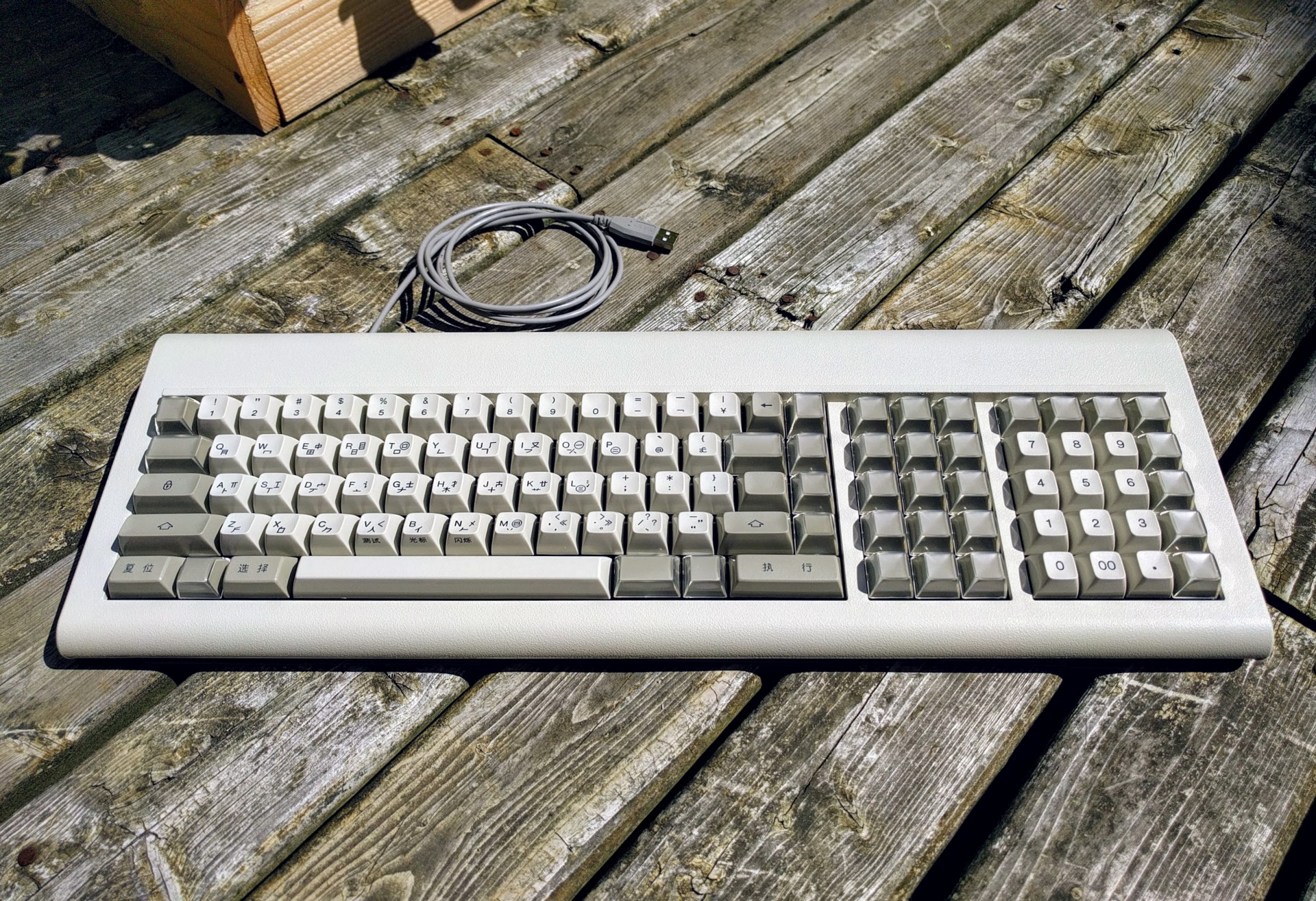
Internal Hasu's converter for IBM 6113442 keyboard
August 27, 2018
Building a reversible, internal USB converter for the IBM 6113442 “Pingmaster” with a Teensy 2.0 and Hasu’s TMK firmware.
Necessary equipment
- teensy 2.0 (or pro micro)
- mini usb cable
- floppy disk power connector
- two 1kOhm resistors
- soldering tools
- screwdriver - philips head
Nice to have
- teensy 2.0 with header pins
- breadboard
- multimeter with continuity tester
- “helping hands” soldering aide
References
- https://geekhack.org/index.php?topic=54706.0
- https://github.com/tmk/tmk_keyboard/tree/master/converter/ibm4704_usb
- https://deskthority.net/post366609.html?sid=7a2baf4f648e5a8125e402d8e2671415#p366609
- https://www.pjrc.com/teensy/loader.html
- http://www.tmk-kbd.com/tmk_keyboard/editor/unimap/?ibm4704_usb_rev1_alps
Open the keyboard and remove the original cable
When removing screws, make sure to put them in a tray/dish so you don’t lose them.
- Flip the keyboard upside down and remove the four screws
- Flip the keyboard right side up, slide the top plate forward, and lift from the rear
- Remove two screws:
- Screw securing the cable
- Screw connecting the cable’s shield ground to the keyboard plate
- Disconnect and remove the cable
Prepare the floppy power connector
- Test to ensure the connector you have fits on the keyboard’s internal header (4 pins)
- Cut the connector leaving 3-6 inches of wire attached to the floppy header
- Strip about 0.5 inches from the end of each of the 4 wires
Prepare the keyboard controller
- Visit http://www.tmk-kbd.com/tmk_keyboard/editor/unimap/?ibm4704_usb_rev1_alps and customize the layout as desired
- Download the output .hex file
- Use teensy loader to write .hex file to teensy board
(Optional) Test on a breadboard
- If you have a breadboard-compatible teensy, plug it in to your breadboard
- Add pullup resistors:
- 1k between Vcc and Data (PD0 on the teensy)
- 1k between Vcc and Clock (PD1 on the teensy)
- Plug the floppy power cable into your keyboard
- Plug the wires from the power cable into your breadboard
- When looking at the keyboard from the normal orientation, the pinout of the header for the cable is:
- Pin 1 (top): Clock - connect to teensy PD1
- Pin 2: Data - connect to teensy PD0
- Pin 3: Ground - connect to teensy ground
- Pin 4 (bottom): 5V Power - connect to teensy Vcc
- Attach the usb cable from computer to teensy
It will take up to 10 seconds before the keyboard becomes available.
An easy way to test if the keyboard is receiving power and working is to increase the volume of the beeper. If pressing keys produces beeps, then the board is powered on and working. If there are no beeps then there may be a problem with the beeper, the keyboard, or the converter.
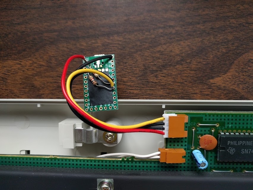
Solder the converter
- Test fit the wires from the floppy header into the teensy
- When looking at the keyboard from the normal orientation, the pinout of the header for the cable is:
- Pin 1 (top): Clock - connect to teensy PD1
- Pin 2: Data - connect to teensy PD0
- Pin 3: Ground - connect to teensy ground
- Pin 4 (bottom): 5V Power - connect to teensy Vcc
- Determine how long you need the leads on the pullup resistors to be to fit correctly over the teensy without shorting anything
- Solder a pullup resistor between wires 1 and 4 of the floppy header (Clock to Vcc)
- Solder a pullup resistor between wires 2 and 4 of the floppy header (Data to Vcc)
- Clip any excess wire from the resistor leads
- Solder the wires to the teensy according to the pinout above
- Attach the usb cable from computer to teensy
It will take up to 10 seconds before the keyboard becomes available.
Troubleshooting
- Make sure your .hex file is compiled for the right architecture (teensy 2.0 has an ATMega32u4 which matches hasu’s “rev.1” converter)
- Double check the wiring:
- Teensy pin D0 connected to a pullup resistor and the second wire on the floppy header
- Teensy pin D1 connected to a pullup resistor and the first (top) wire on the floppy header
- Teensy Vcc connected to both pullup resistors and the fourth (bottom) wire on the floppy header
- Teensy GND connected to the third wire on the floppy header
- Check for shorts:
- Make sure the resistor wires aren’t touching each other or any of the contacts on the teensy (use electrical tape to separate)
- Make sure no solder blobs have bridged a gap between two pads on the teensy
- On a breadboard, make sure there is continuity between the teensy pins and anything connected to them
- Try a different usb port and make sure to wait 10 seconds or longer for the keyboard to initialize
Install the converter and close the case
- Plug the usb cable into the teensy and fit the teensy into the space to the left of the cable outlet
- Loop the usb cable around (under the keyboard plate) and out through the cable outlet
- If the usb cable is much narrower than the original cable, the retaining clip may not hold the cable snugly
- If necessary, cut a small piece of cardboard/boxboard and place it under the retaining clip and over the cable
- When the retaining clip is screwed in, it should firmly hold the usb cable in place
- Replace the top shell, making sure all of the front and rear clips are solidly in place
- Replace the 4 bottom screws